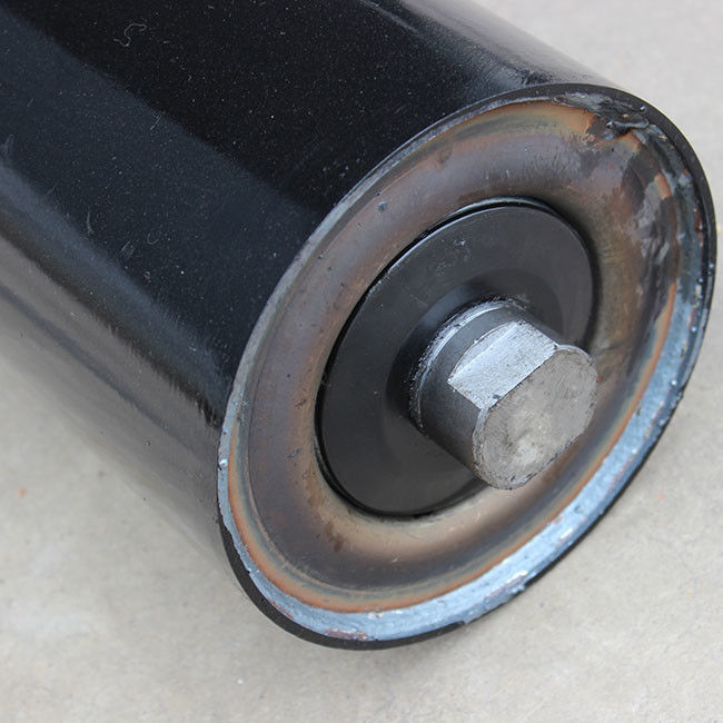
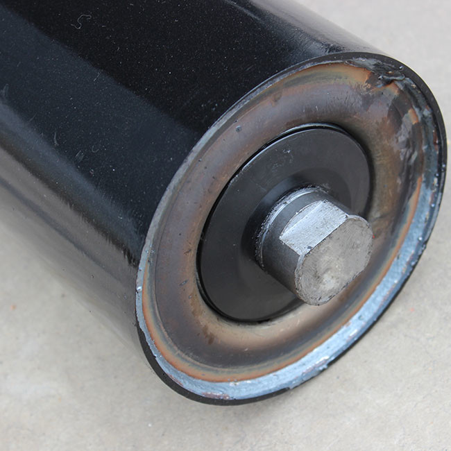
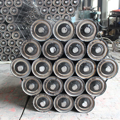
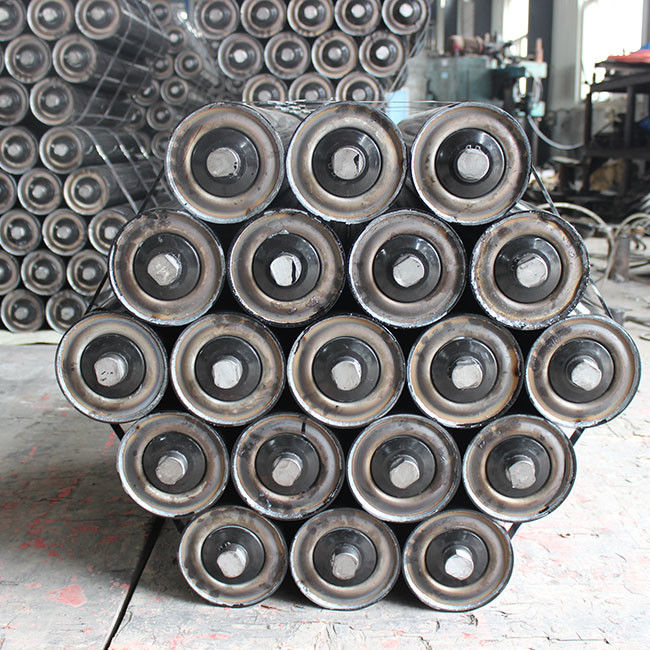
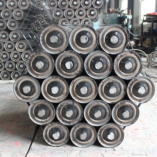
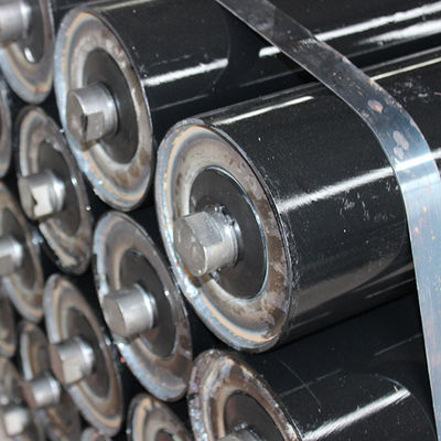
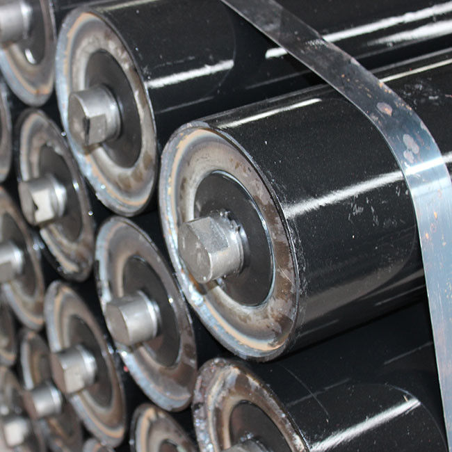
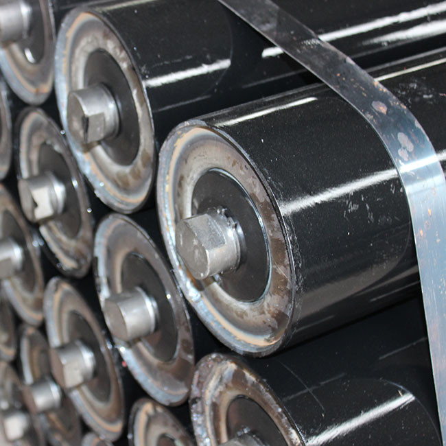
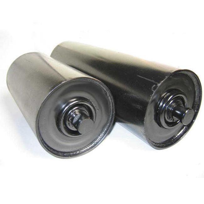
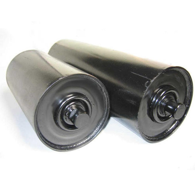
Effective Sealing Grooved Dustproof Conveyor Carrier Roller
Contact Person : Tony
Phone Number : 008613623381923
WhatsApp : +8613623381923
Detail Information |
|||
Specification: | Φ89;Φ108 | Material: | Iron |
---|---|---|---|
Type: | Grooved | Color: | Black |
Highlight: | waterproof conveyor carrier roller,durable conveyor carrier roller,89mm conveyor carrier roller |
Product Description
Cost Effective Conveyor Carrier Roller Durable Strong Good Sealing Grooved Waterproof
In the typical light conveyor roller, the supporting shaft is arranged in the round hole of the frame at both ends and the split pin is used for axial positioning. In the process of application, the two ball bearings of the idler are very easy to attack and damage. The reason of the accident lies in that the two ends of the roller shaft only adopt the complex cotter pin positioning, which can not effectively avoid the axial movement of the shaft. Because the load on the conveyor belt often changes, even the load is deviated, the conveyor belt often applies alternating axial force to the roller shaft during operation, which makes the idler rotate around the shaft while moving left and right, which results in bad bearing working conditions and rapid damage of bearings.
The utility model is intended to provide a conveyor belt idler to handle the wearing performance of the roller bearing in the prior art. The conveyor belt roller in the scheme includes a support frame connected with the supporting shaft and both ends. The supporting shaft is connected with the conveyor belt through the bearing. The supporting shaft is characterized in that the support frame is equipped with a tooth opening groove with a width less than the diameter of the supporting shaft, and the arc surface of the end of the supporting shaft is provided with a plane section matching with the tooth opening groove, and the absolute side of the plane plane and the end of the support shaft is provided with an absolute plane with the two support frames For parallel limit surface, the spacing of the corresponding limit surface at both ends of the bearing shaft is equal to the spacing between the two supports. The supporting shaft is clamped in the tooth opening groove of the support frame through the plane cutting surface.
Enter Your Message